Software Subsystem
Electronics Design
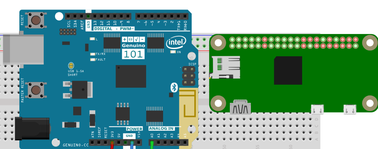
To meet our goals of achieving and enabling swarm behavior one of our first goals was that the fish would have a camera. This would serve as its key way of receiving other data from fish in a swarm. We already had raspberry pi cameras that are a reasonable form factor and low cost (<$10). This choice then dictated our choice of microcontroller. Early in our design we were developing systems around an Arduino everyone had access to one. Once the camera was specified we realized that the Raspberry Pi Zero was a natural choice. Not only would we have the larger amount of computing power and trivial connection to a camera - the computer could be programmed via wifi(SSH). The physical form factor of the board was also ideal, the thin board was feasible to fit within our target fish size and had GPIO pins to control other electronics just as the Arduino had. The below visual shows a comparision.
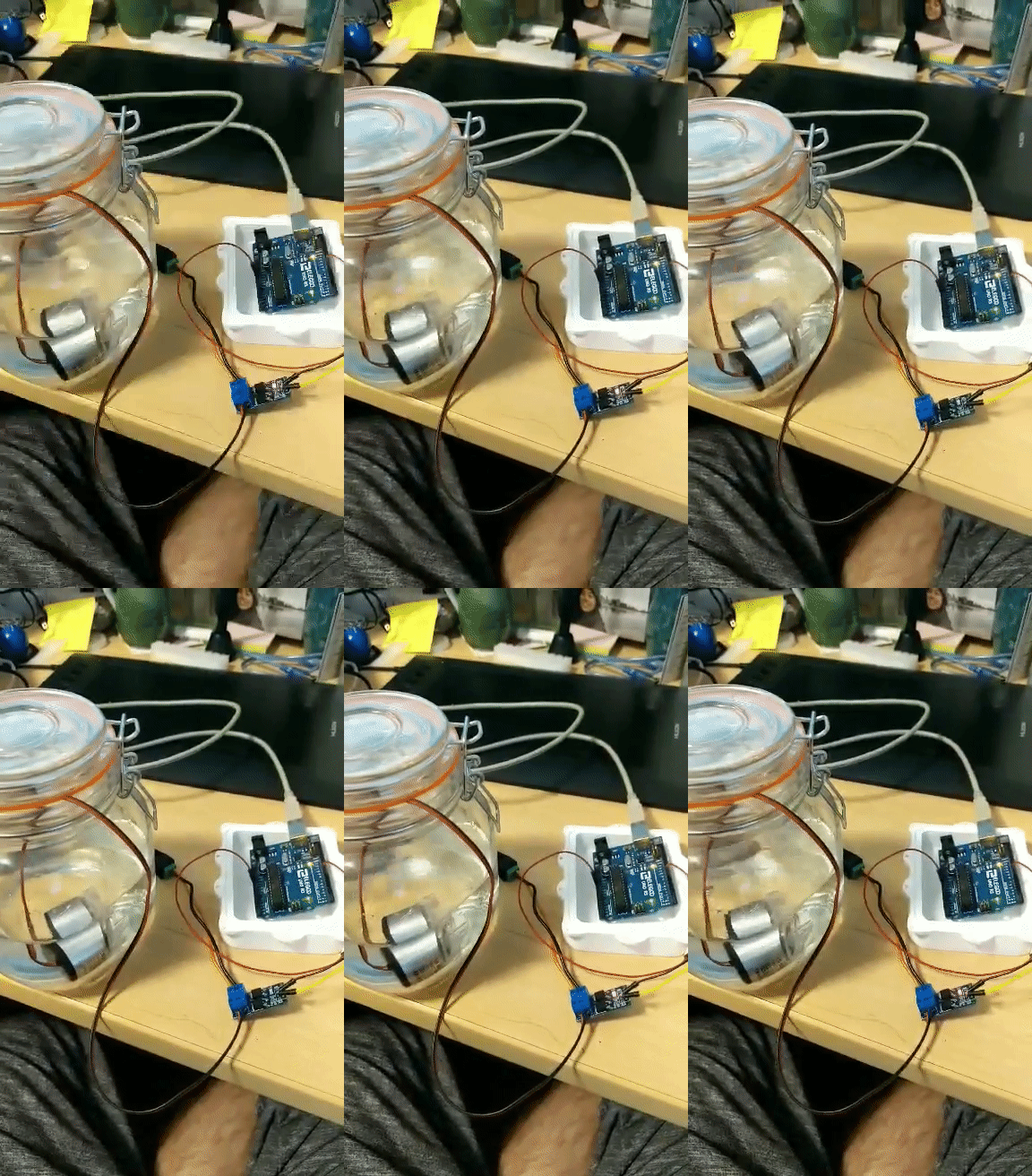
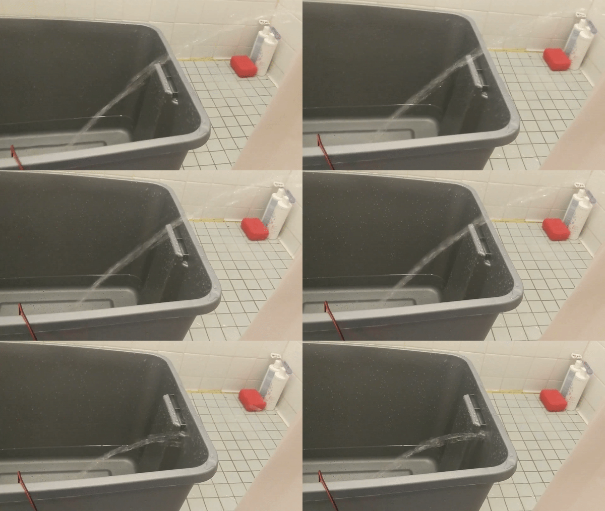
Our original design called for the control of a small servo in addition to a 12V centrifugal pump. Since we were designing the tail in tandem it was unclear the speed at which we would need to operate the pump and figured that it would be best if we were able to control it with a motor controller of sorts as opposed to on/off. Due to our size constraints we settled on using a MOSFET motor driver board that accepted a PWM(pulse width modulation) signal to output varying speeds of our pump this was smaller than any other driver boards that would handle our pump. This can be seen below, as the pump switches from on to off and from full speed to half speed.
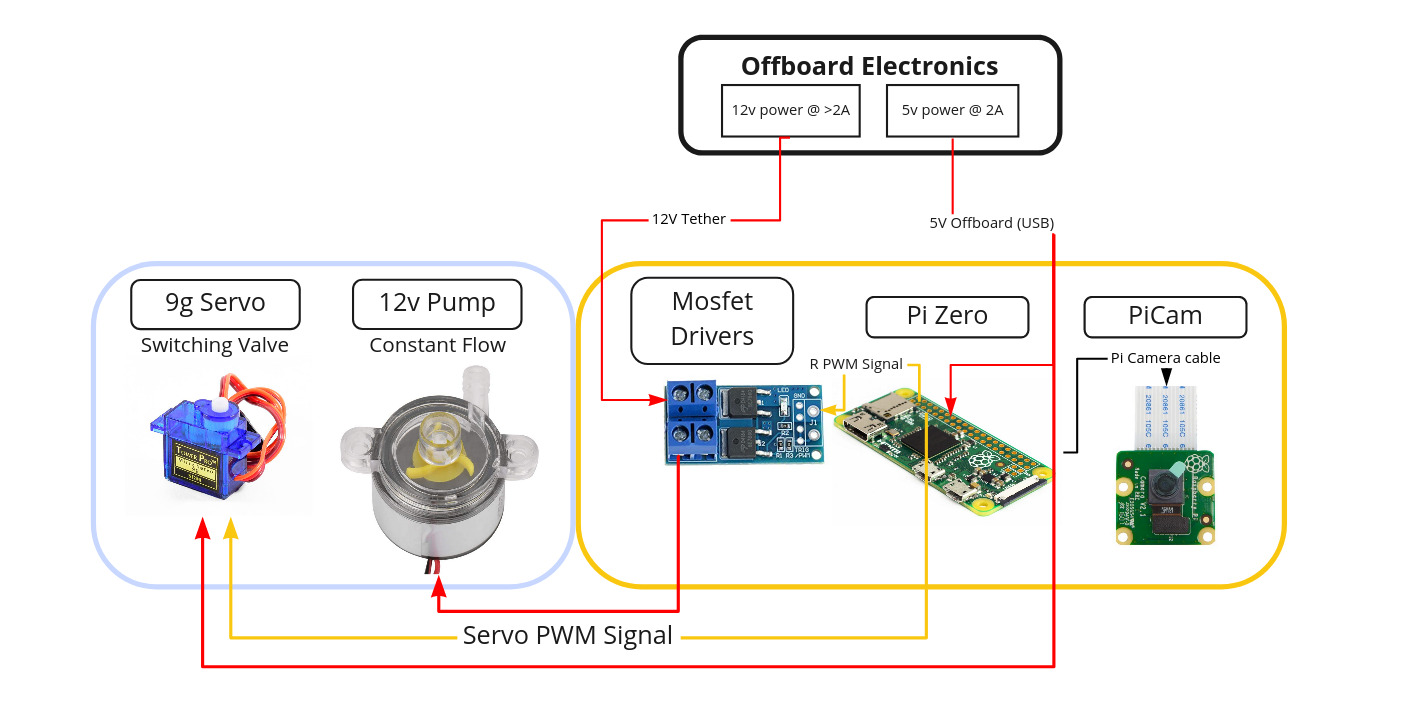
Our base level system is captured in the below diagram
Testing Scripts and Control Development
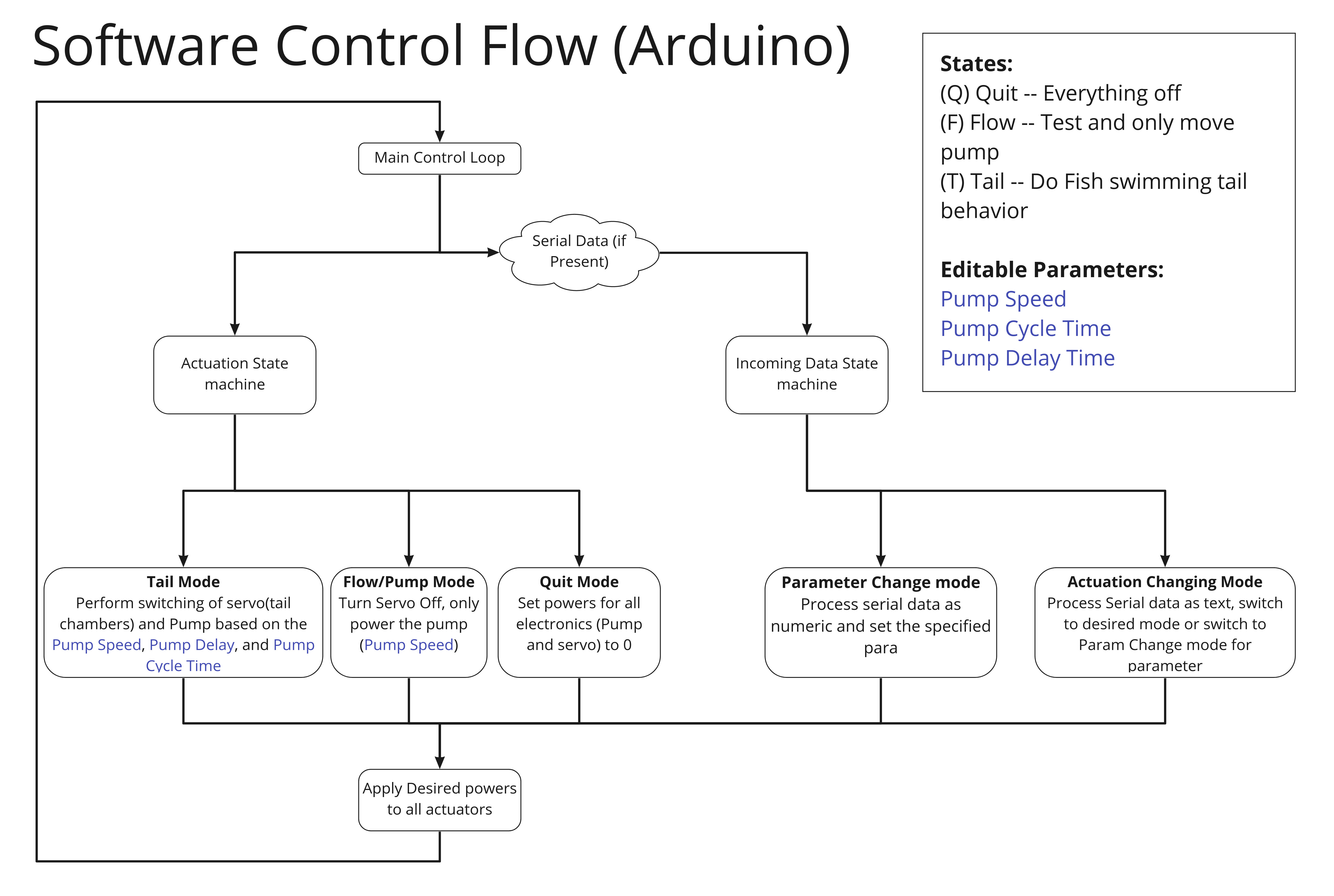
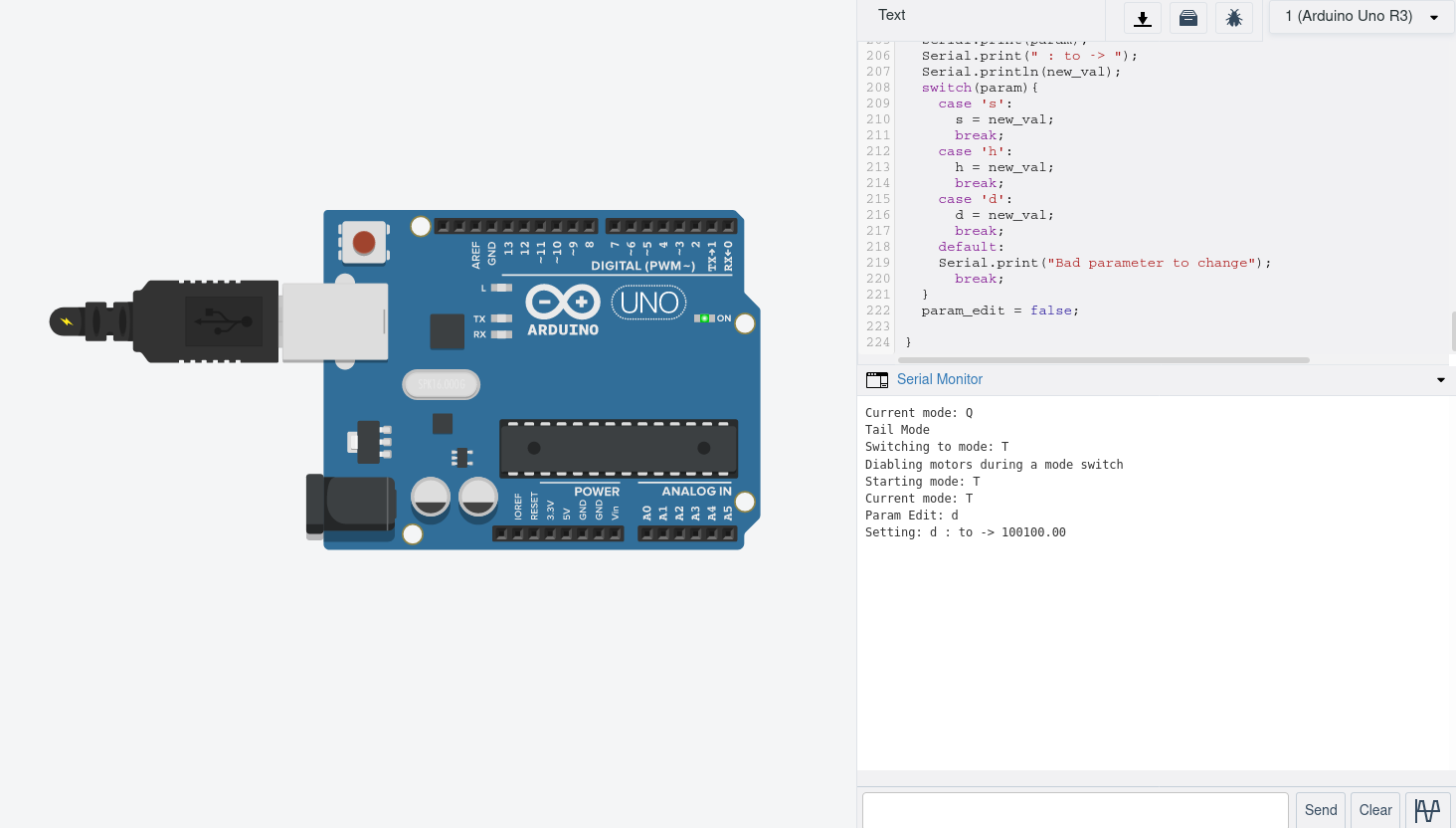
Due to the fact that the development of the fish was happening in multiple places at once. We opted for a barebones testing script to be written in/for Arduino since none of us had experience using the GPIO pins on the RPI and we all had experience with Arduinos. The testing script developed was meant to help understand what settings should be used for a final fish tail operation. This includes everything about how the tail actuates. The script was written in such a way that the pump flow-rate, duration/cycle speed, and delays could change via user input see the below flow diagram and screen grab of the code running.
After this base code was running exploration into the control via RPI was explored. There are several GPIO libraries intended to make interfacing with the GPIO pins in Python easier. GPIO Zero seemed to have reasonable documentation and looked to support all the features that I thought I would need and more.
After some trial and error we were able to interface with the MOSFET drivers via several of the PWM pins on the Pi. This system was fleshed out to have control over the fish’s tail parameters (similarly to the aforementioned Arduino code) and was at a point ready for operation on the fish. The processing of the pi camera image was not done yet, but there were a worth of examples that we did not devote time to it.
The final code can be accessed here: