Actuation
In order to make our fish move, we need to find a way to physically actuate it and have it controllable by some sort of “brain.” This page documents the various methods we tested to actuate our fish, and documents the results from creating each of these systems.
Switching Pump - Iteration 1
SoFi, the robotic fish we are basing our project off, got good results from using a custom gear pump. However, they note that this method of actuation requires a lot of power to operate and is rather energy inefficient since it requires regularly switching the motor direction back and forth [1]. Since we only had access to consumer-grade 3D printers, we weren’t confident in our print tolerances being sufficient to create a gear pump like in their design. In another one of their papers on SoFi, they discuss the potential for creating a pump design that could quickly switch the inlet and outlet flows by only using continuously rotating parts [2].
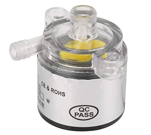
The first thing we attempted to do was to re-create this setup, but customize the parts to fit the geometry of our half-scale fish body. We ultimately purchased this submersible 12V pump, since its flow rate and pressure (estimated from its rated max lift) seemed sufficient for our needs. (Amazon link)
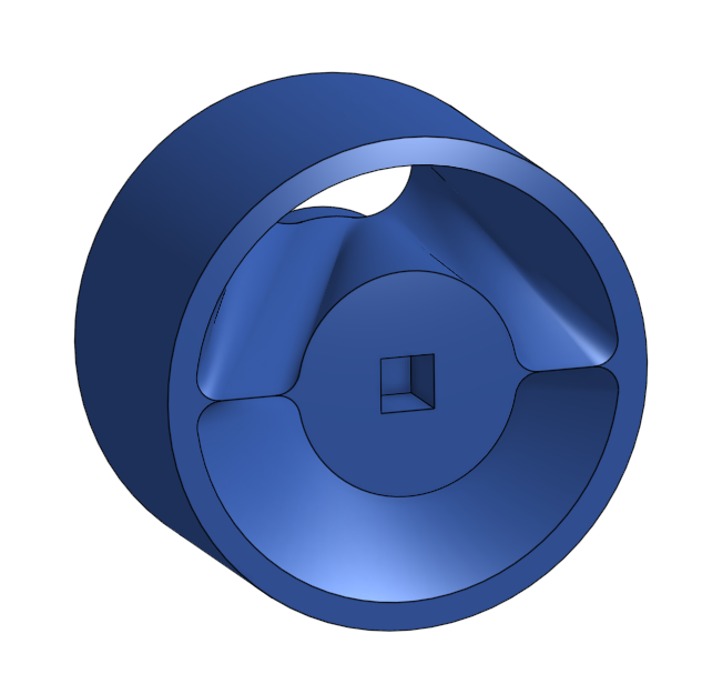
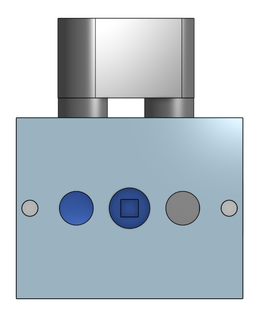
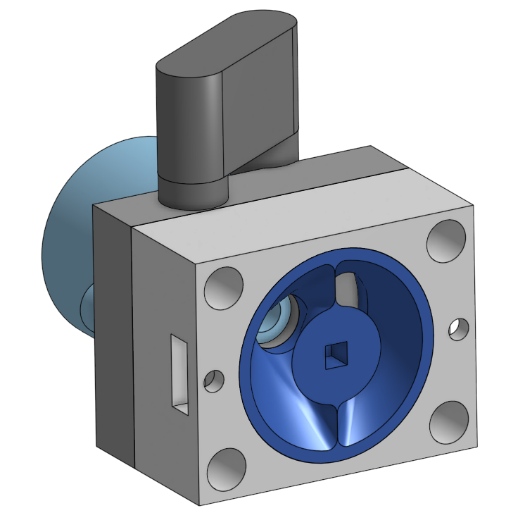
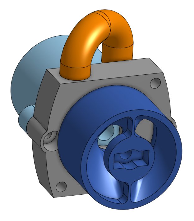
We then created a valve based on the design for a two-way valve attachment to a centrifugal pump as proposed in [2]. For this initial test, the valve was designed to be manually driven by a screwdriver or something similar, so we left a square hole where it would normally mount to a servo.
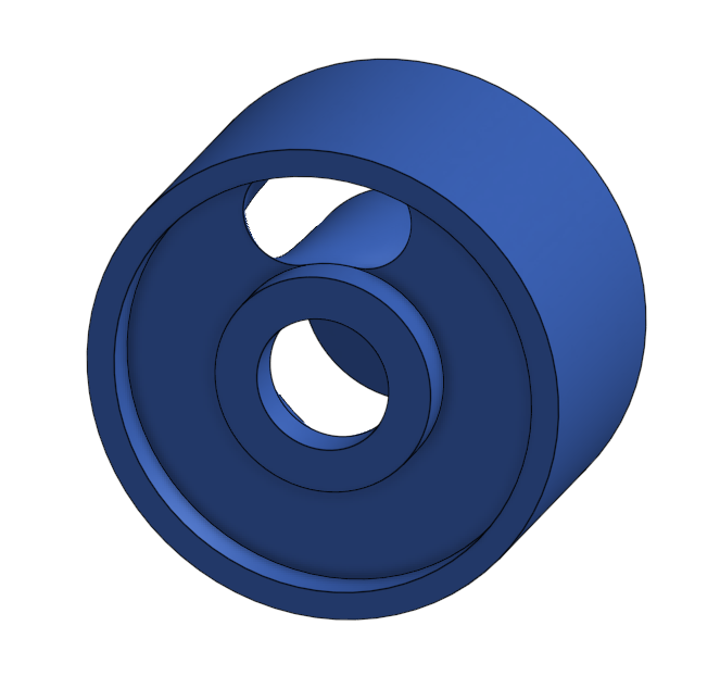
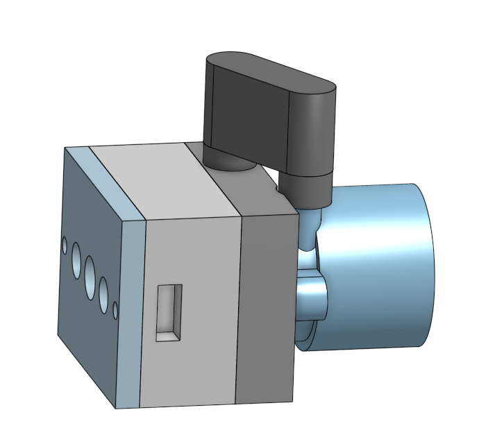
To route water from the pump through the valve, we created a housing for the assembly.
Testing & Results
We 3D printed these parts and tested the assembly in a large bucket of water. It’s a bit difficult to tell in the video feed, but if you look closely at the bumps created by the water flow to the left and right of the screwdriver, you can see that the water flow does indeed switch.
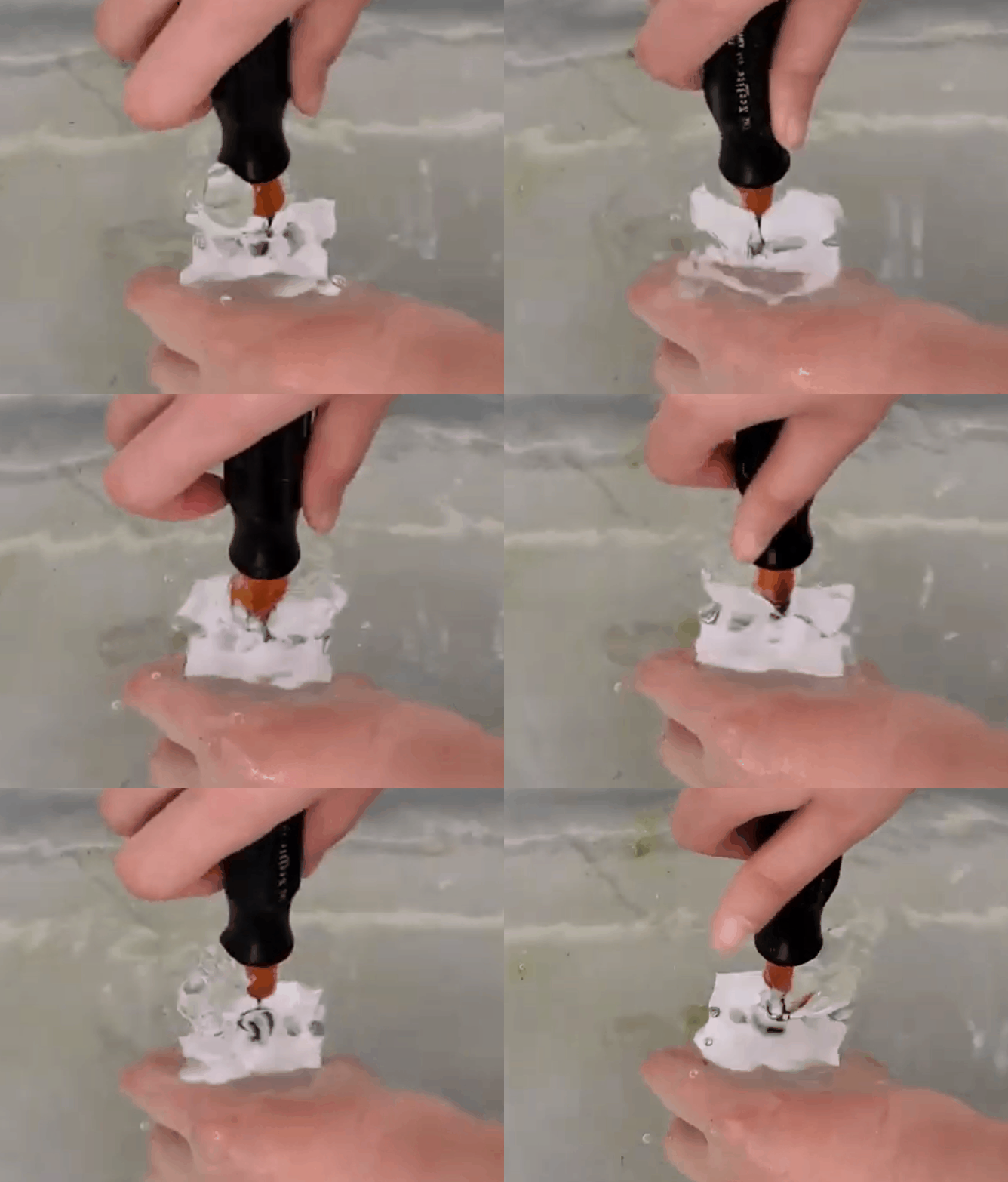
It’s worth noting that the valve took quite some force to turn, and I don’t think most servos would be able to use this assembly as-is. This assembly was also too wide to properly fit into the fish body, so that also needed to be improved.
Switching Pump - Iteration 2
To improve upon the first iteration of the switching pump design, the geometry of the parts in this iteration were optimized to fit into the space we had allotted to it onboard the fish. We also made the tolerances more generous in this design to ensure that the switching valve could be rotated with a small 9g servo.
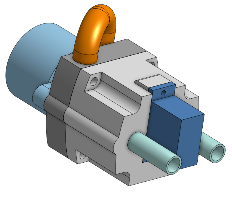
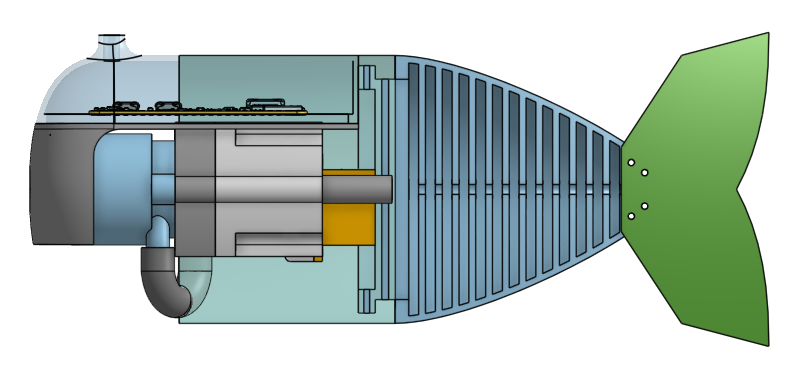
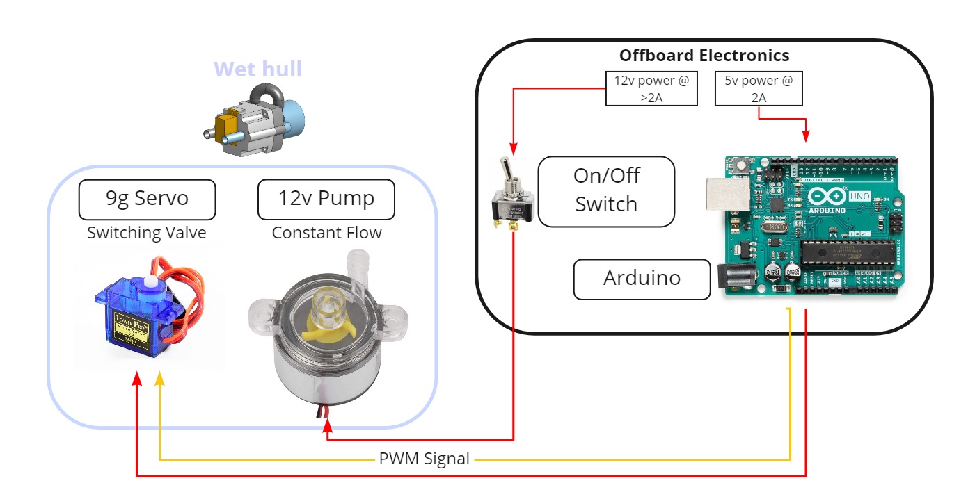
Since we now needed to drive a servo, we needed to add a bit more complexity to our circuit (in our first iteration, the pump was simply plugged into a 12V power supply).
Testing & Results
Once again, we 3D printed these parts and tested the assembly in a large bucket of water. Putting this prototype together required waterproofing our servos since they weren’t rated to be used underwater - for more information about that process, visit our page on waterproofing.
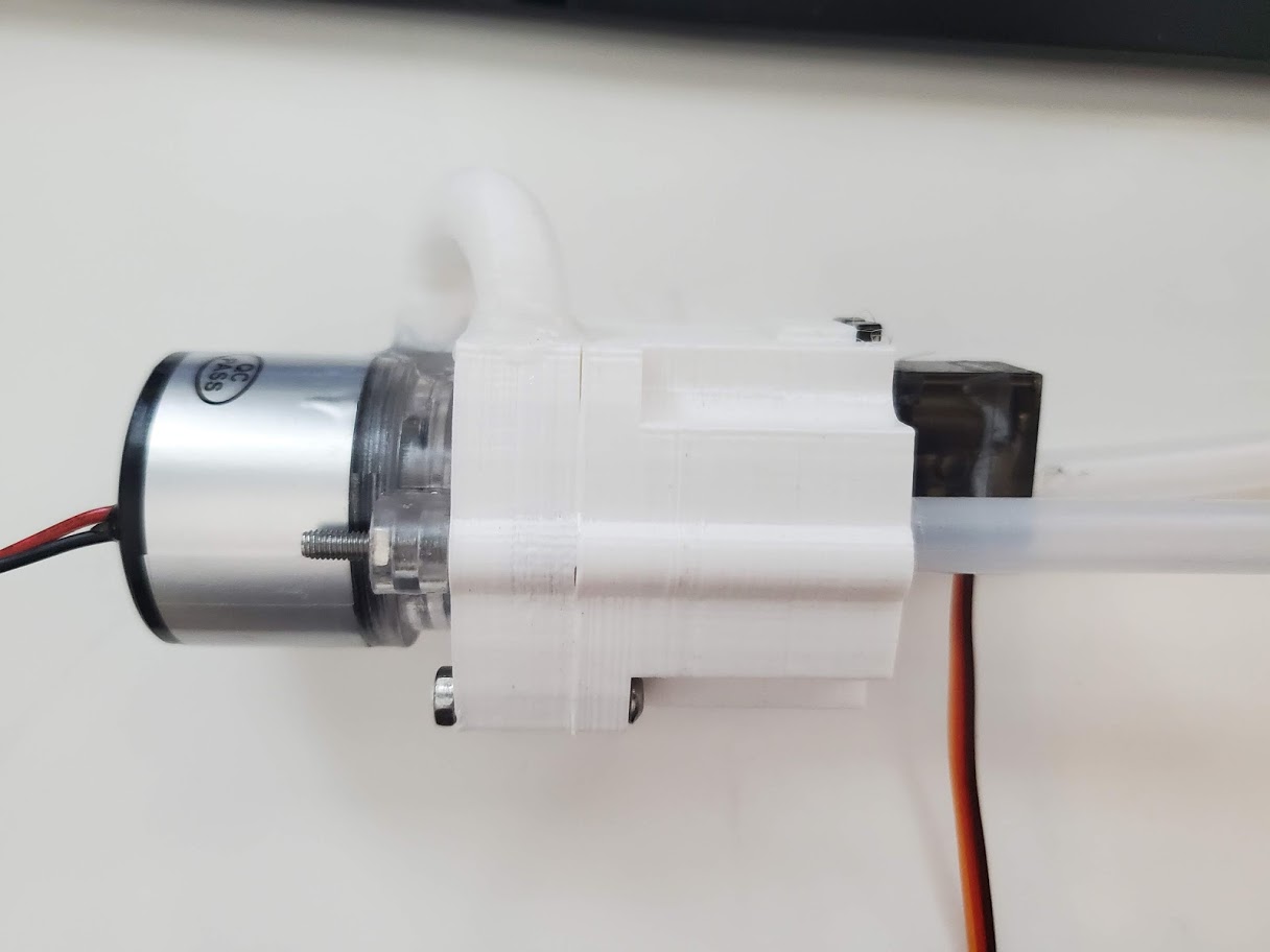
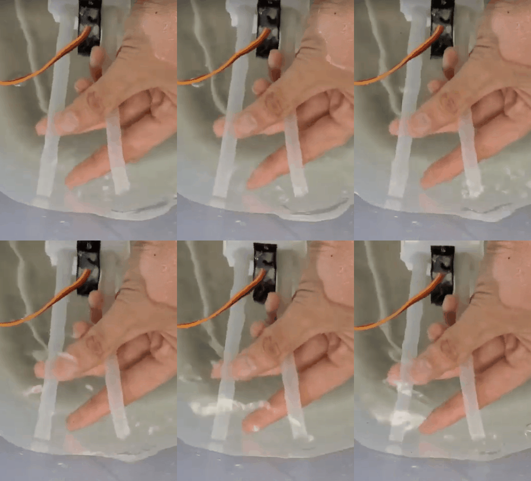
Once again, we were able to control the inlet/outlet switching by rotating the valve, except this time we were able to control it in code instead of by manually turning a valve with the addition of the servo. Unfortunately, this iteration had notably less pressure than the first one to the point where it’s likely not usable. We hypothesize that this is due to the fact that the tolerances between parts for this iteration were a lot more generous, which helped the servo move smoothly but likely led to more internal leaking and a subsequent decrease in pressure as a by-product. To confirm that the loss of pressure was caused by internal and not external leaking, we covered the entire assembly in clear flex-seal, and after this process the outlet pressure remained mostly unchanged.
We were able to get in touch with the creators of SoFi, and they experienced similar challenges even when using resin 3D prints off of an Form3, which has much tighter printing tolerances than we’re able to get from consumer FDM printers. Based on that feedback and from our initial results, we decided to pivot away from the rotating valve idea due to our manufacturing constraints.
Soft Tail Actuation with 2 Pumps
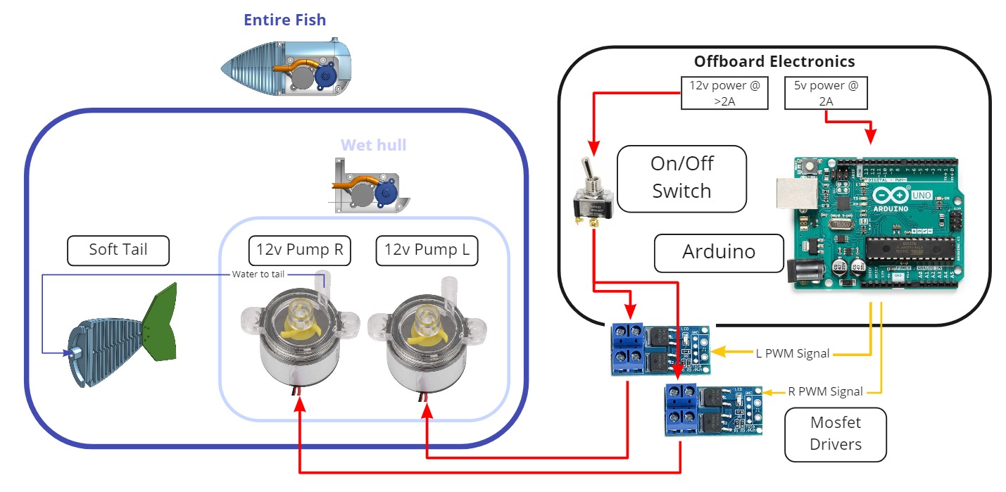
After pivoting away from the rotating valve idea, we decided to pursue a 2-pump setup since our pumps should be able to support the pressure and flow rate needed for tail actuation (we needed 2 pumps because we were using centrifugal pumps, which boast a high flow rate but can’t pump water backwards). Now that we needed to drive each pump independently at precise intervals, we purchased PWM MOSFET driver boards off of Amazon to provide our Arduino with the ability to control the pumps. Our updated system diagram looked like this:
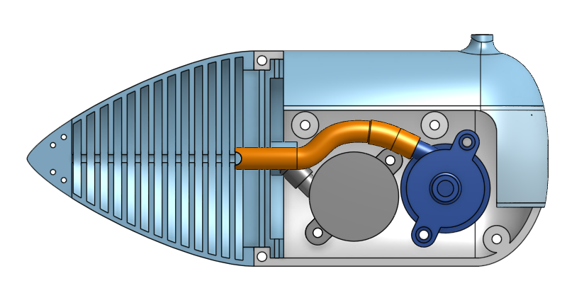
Moving to a 2-pump design also required a redesign of the fish body to include mounts for the pumps. We wanted to eventually create a waterproof hull to support onboard computing hardware, so we decided to mount the pumps low to leave space for a “brain.” Mounting the hardware in this orientation also helped keep our center of mass far lower than our center of buoyancy, which helped with stability. Our updated fish body looked like this:
Testing & Results
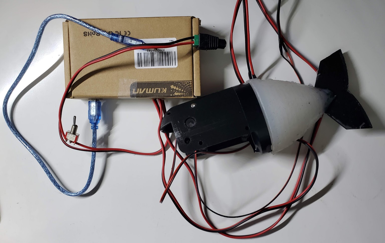
To protect our electronic components from the occasional water splash, we put the Arduino and MOSFET boards in a cardboard box. We added a switch to our 12V power supply that was readily accessible outside of the box for quick pump shut-off as an additional safety in case anything quickly went wrong. We also extended the pump power wires with extra long leads to keep the electronic box as far away from water as possible, which was pretty handy for testing. Here’s what this circuitry looked like:
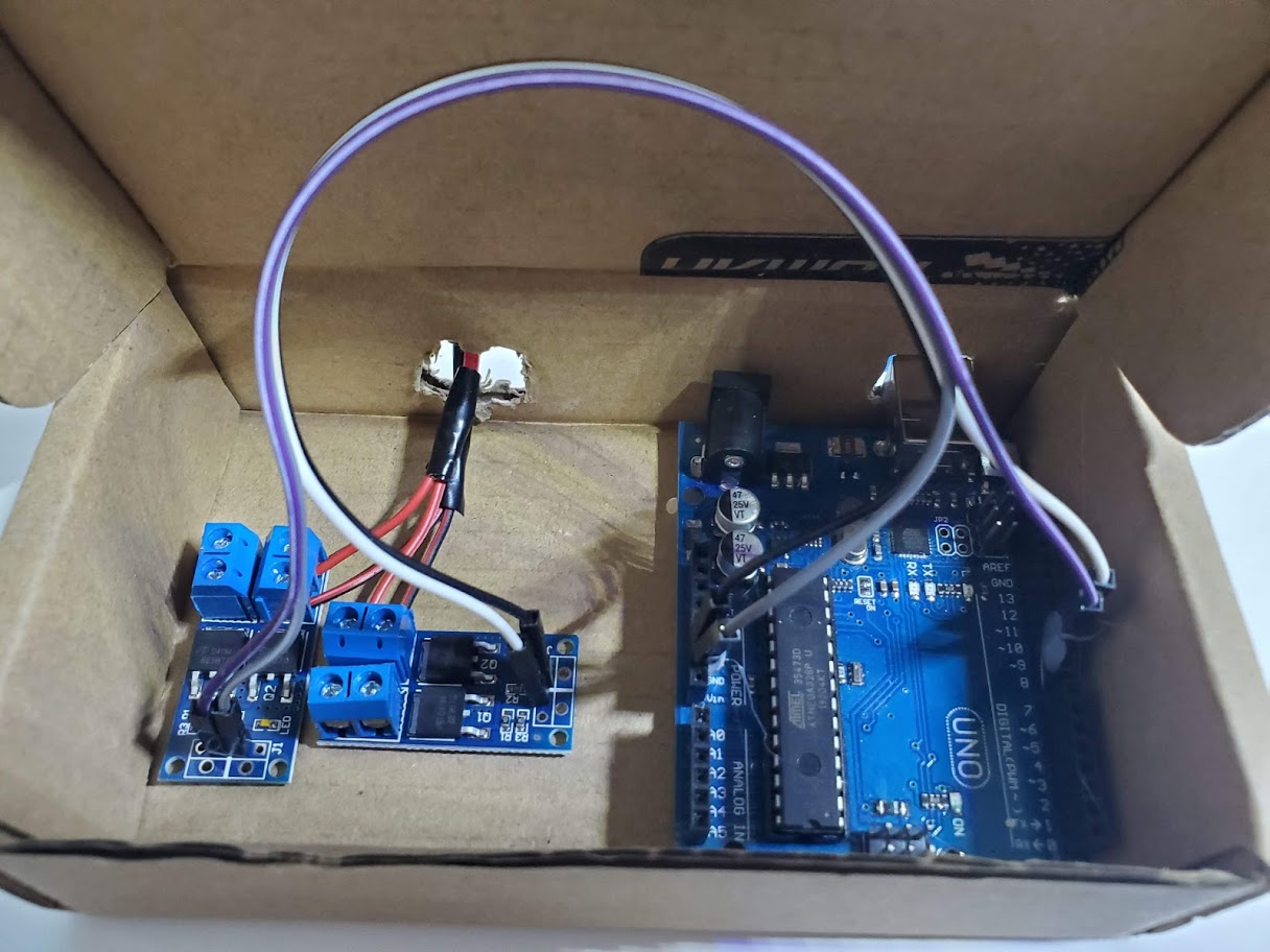
We were able to successfully actuate our soft fish tail using our two-pump setup with an ample degree of actuation. Thankfully, our pump seemed to strong enough to get the full actuation range of the fish tail - in fact, we needed to shut it off early to prevent popping the tail. Unfortunately, our primary bottleneck turned out to be the deflation rather than the inflation speed - we needed to add a delay between alternating chambers to give time for the other side of the fish tail to deflate. Without this delay, both chambers would progressively get bigger over time, which would likely lead to one of the sides bursting if left unchecked.
We tested a range of actuation frequencies and delays, and found that there was a general tradeoff between actuation range and frequency - at a higher frequency, the degree of actuation was less, but at lower frequencies the degree of actuation was much higher. (Note that the balloon was used as a stand-in for the waterproof hull - the waterproof hull is necessary for flotation)
| Frequency | Delay | Visual |
|---|---|---|
| 2 Hz | 300 ms | 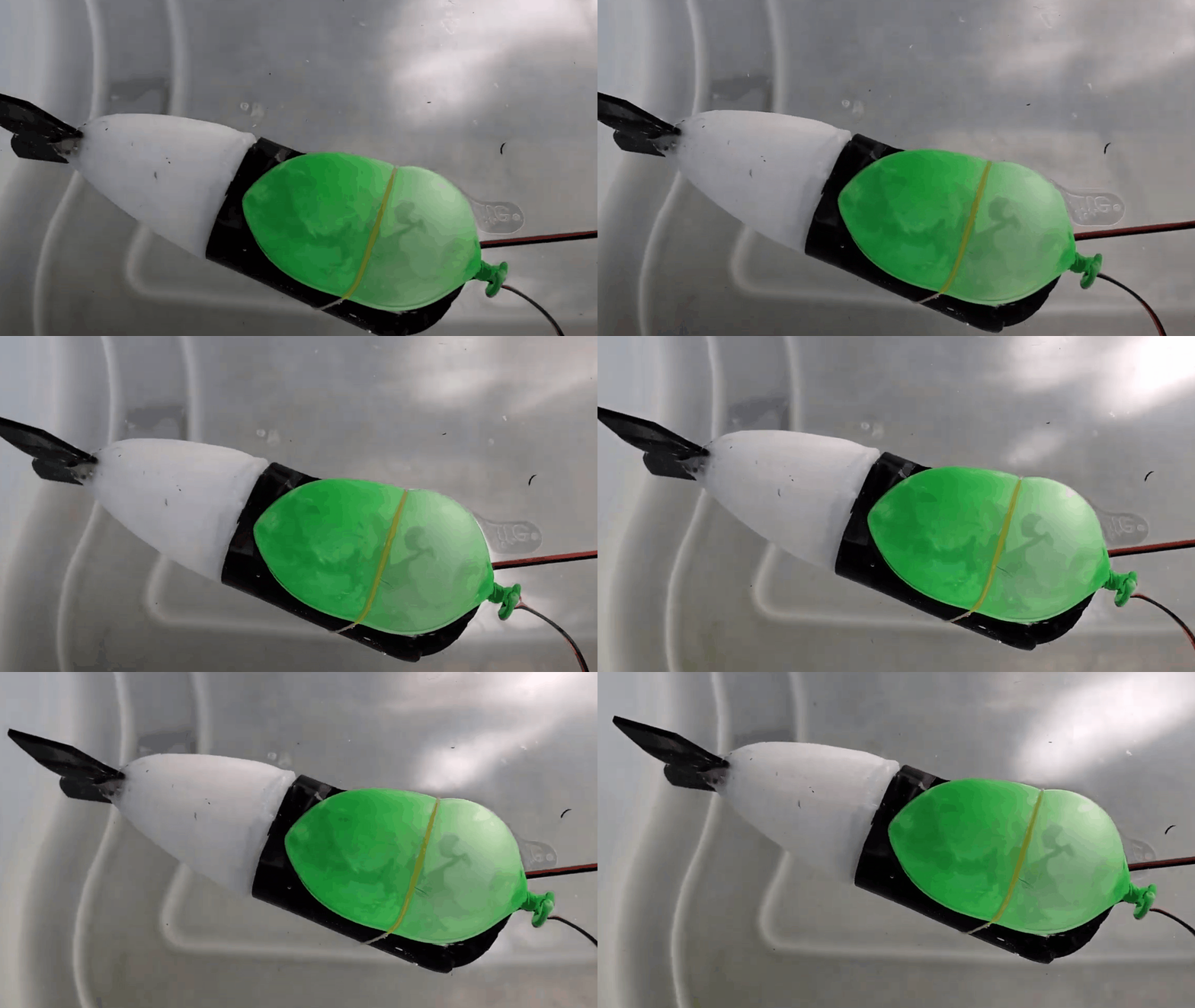 |
| 1.5 Hz | 350 ms | 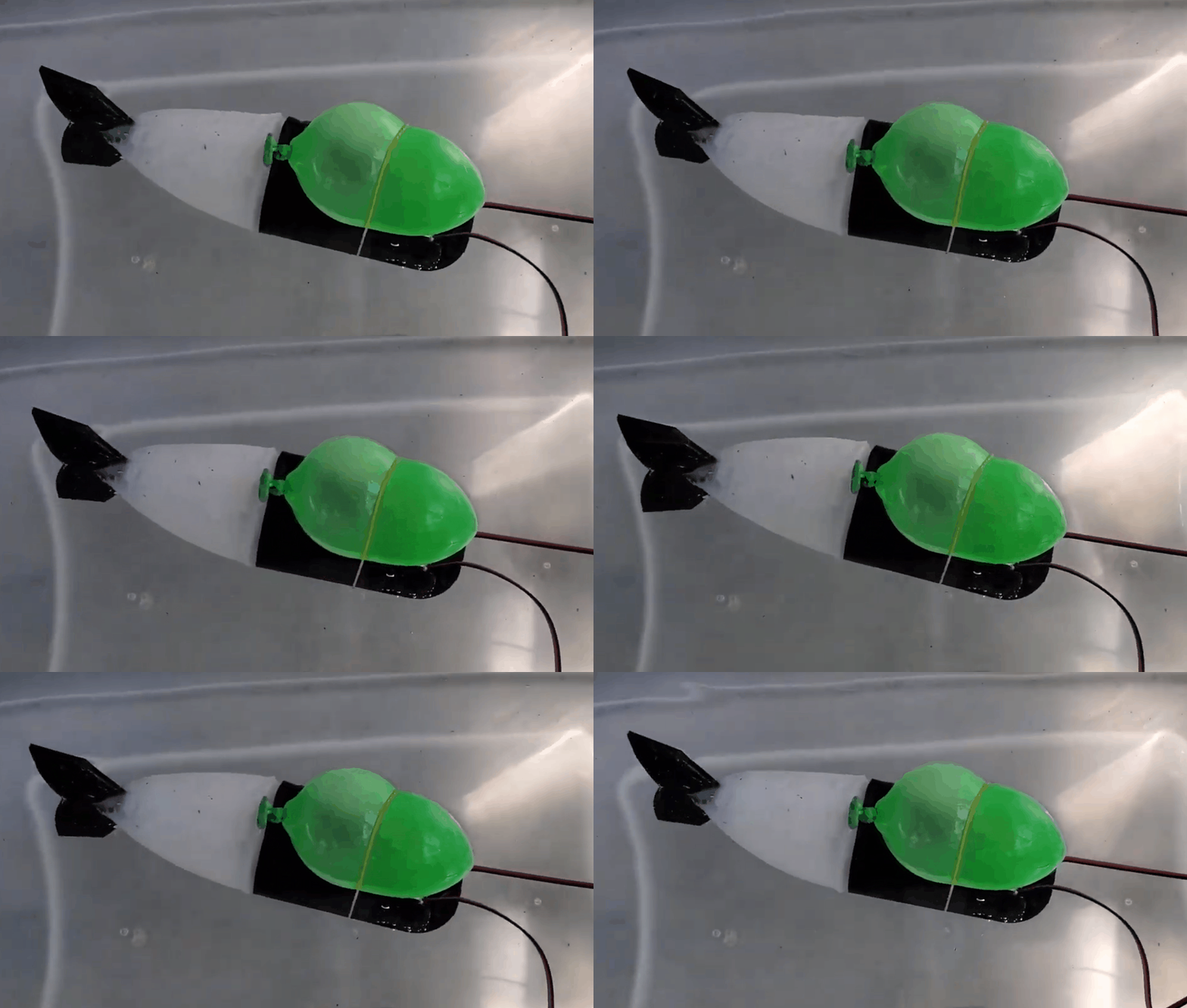 |
| 1 Hz | 500 ms | 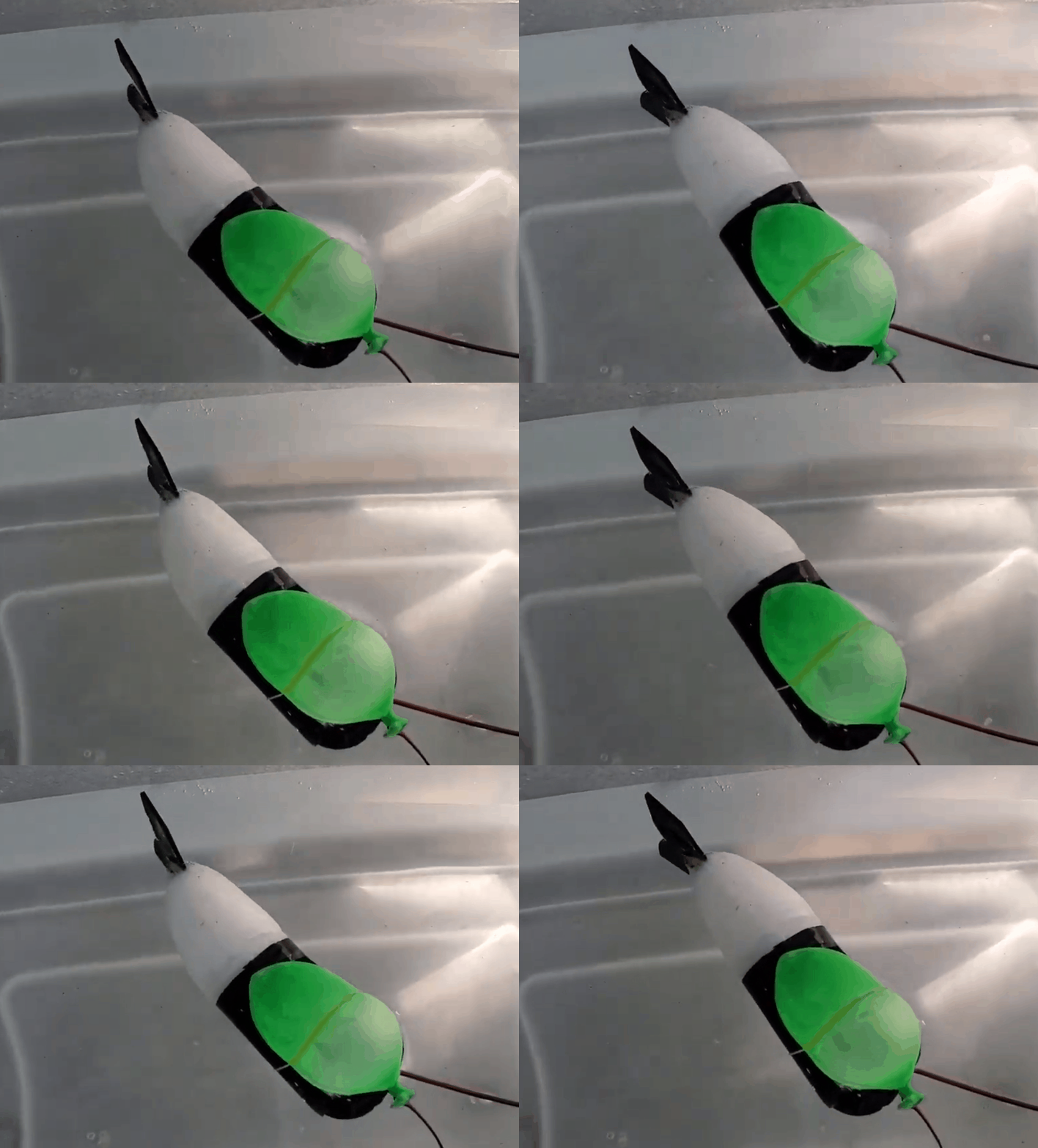 |
| 0.7 Hz | 500 ms | 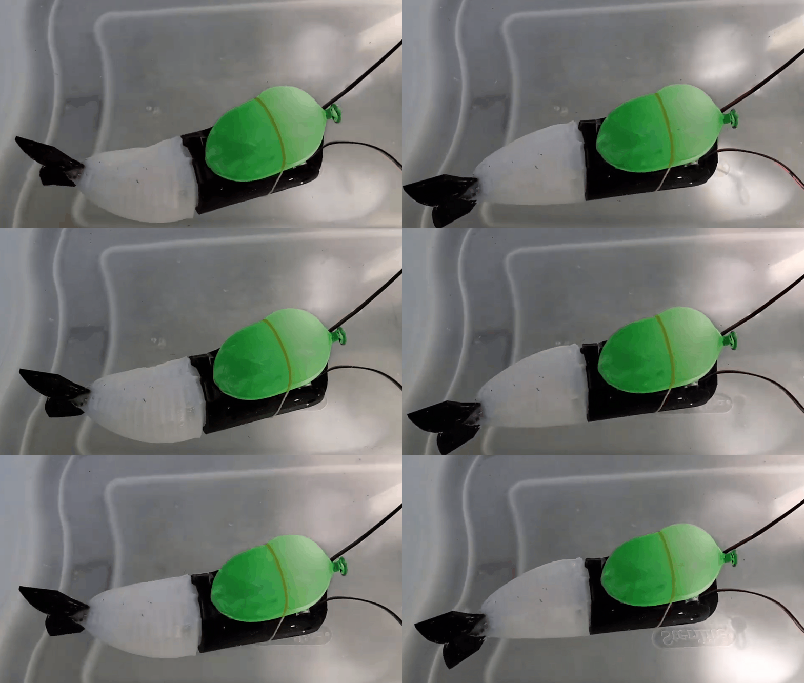 |
| 0.5 Hz | 800 ms |  |
Unfortunately, we were unable to find values of actuation frequency and delays that allowed our fish to swim forwards - with a high frequency, the tail didn’t actuate enough to generate thrust, and at low frequencies the tail movements were too far apart to translate to forwards motion.
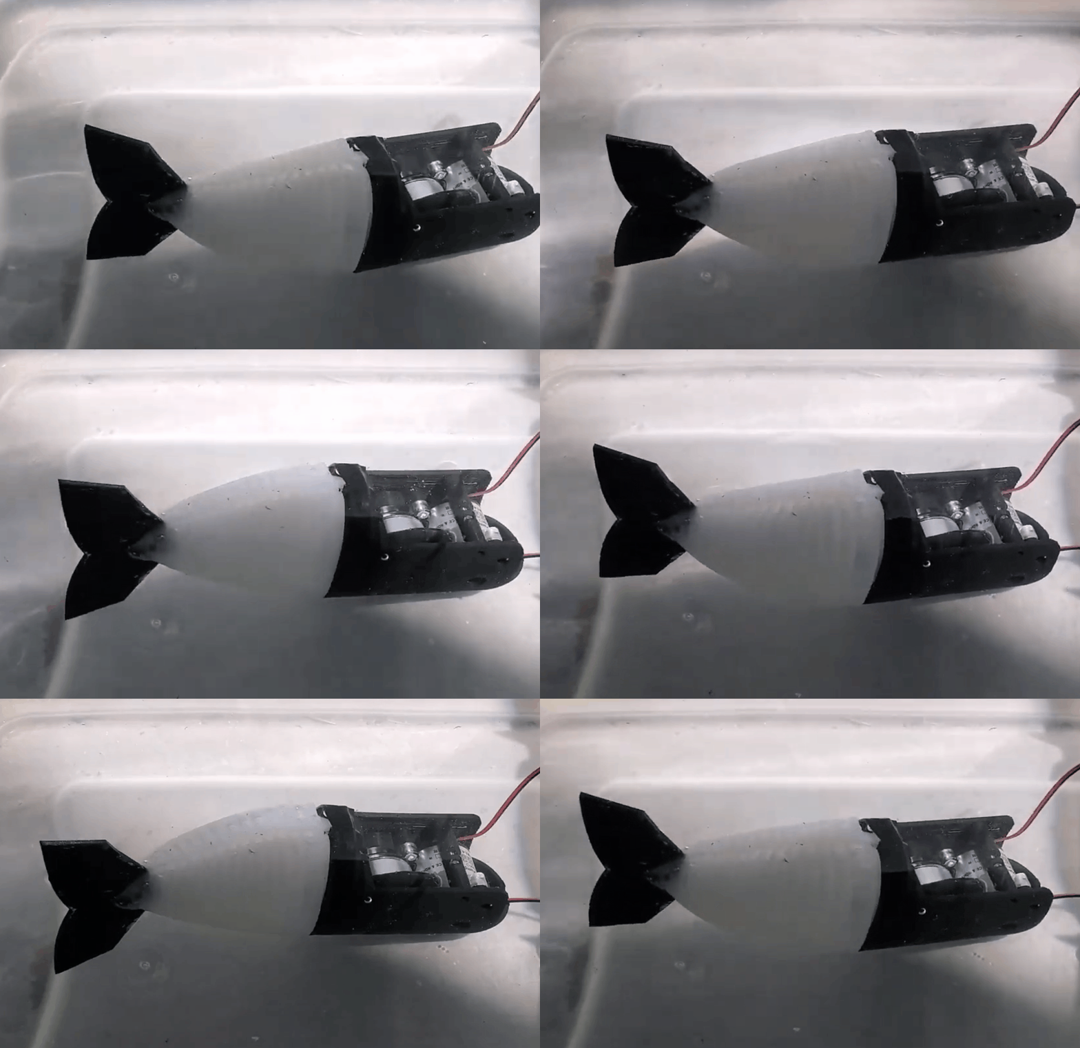
After witnessing the extent to which leaks affected our pump’s performance in the earlier pump iterations, we were surprised to find that we were limited by deflation rather than inflation rates. In hindsight though, this makes a lot of sense - with only one place for water to flow in and out of the chamber, the water will passively flow out of the chamber at a much slower rate than when a pump is actively pumping water in. In order to fix this design, we’d need to either find a way to actively pump water out of the chamber as quickly as we can pump it in, or add an outlet valve big enough to make the passive deflation rate match the active inflation rate.
For more information about the soft tail design and fabrication, visit this page: Soft Tail Design
For the code that we used to test this setup, visit our software subsystem page: Software Subsystem
Hard Tail Actuation
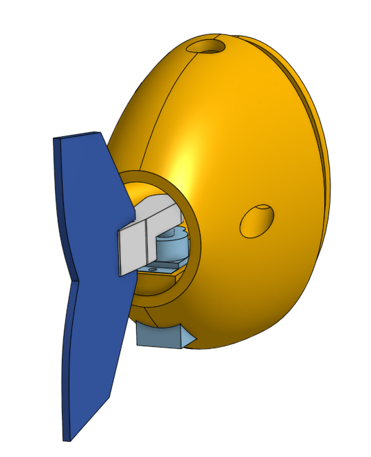
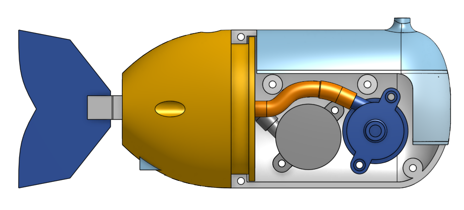
Although the primary focus of our project was to create a fish that swam with a soft robotic tail, we wanted to create a fish that could swim in a controlled manner even if it meant not necessarily using the soft tail. This version of the fish replaced the soft tail with a servo-driven tail, which made it much easier to control. We left the two pumps installed in this version to serve a dual purpose: 1) as ballast, and 2) to enable faster swimming speeds than would otherwise be possible with the servo alone.
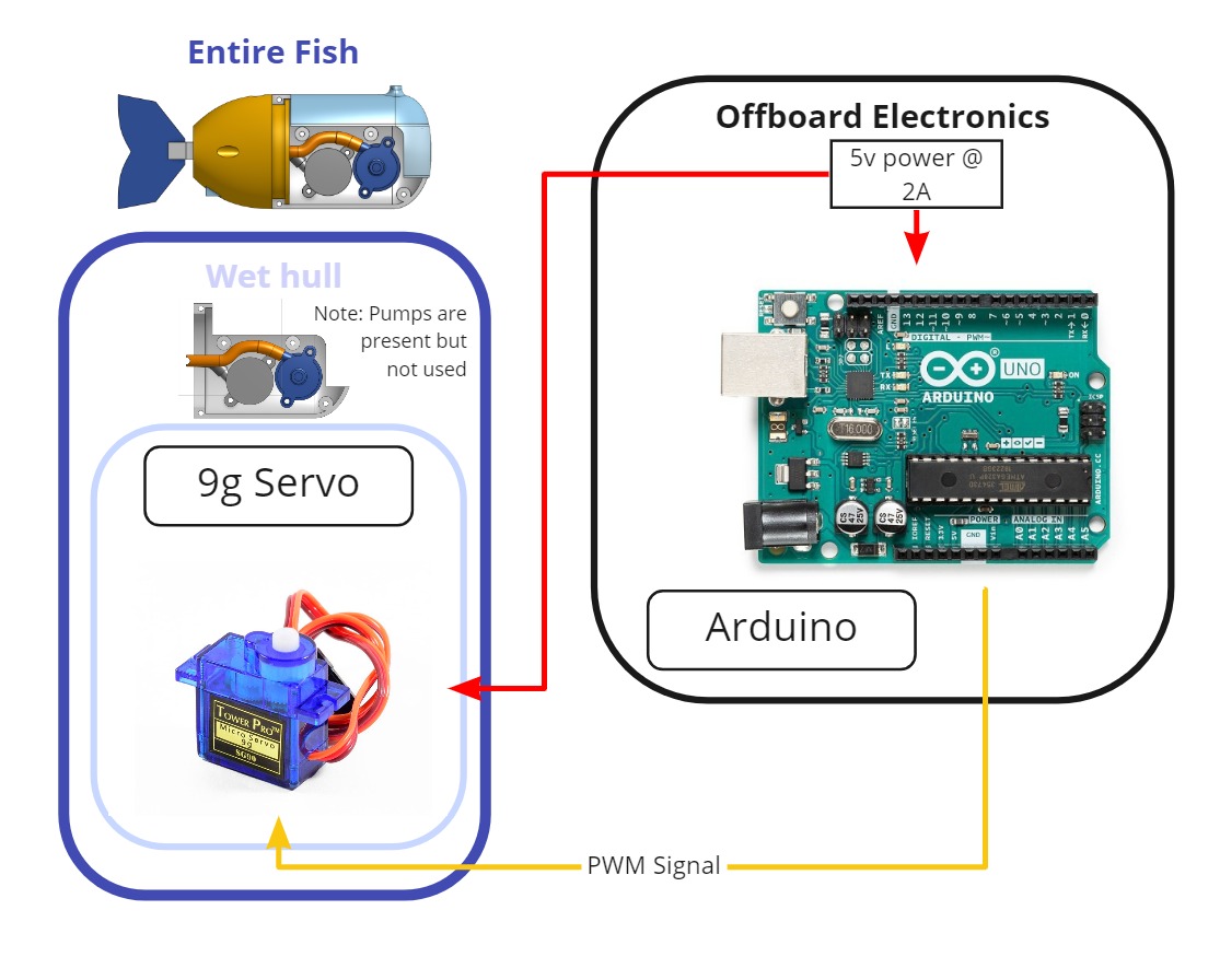
Testing & Results
We were able to get a good swimming motion with the hard fishtail, and it was able to swim around the test bin despite being pulled back by the tether. Now that we had a fish swimming, we were able to fully realize the effect of the tether on the fish’s dynamics - the tether acted a lot like a spring, and after de-powering the fish it would generally return to the same location it started in (unless the tether shifted while it was swimming).
Just for fun, we also wondered what would happen if we tried using only the pumps for swimming. This resulted in a very quick-moving fish, but it’s motions were very different from a fish - at this point, it was basically a just a submarine.
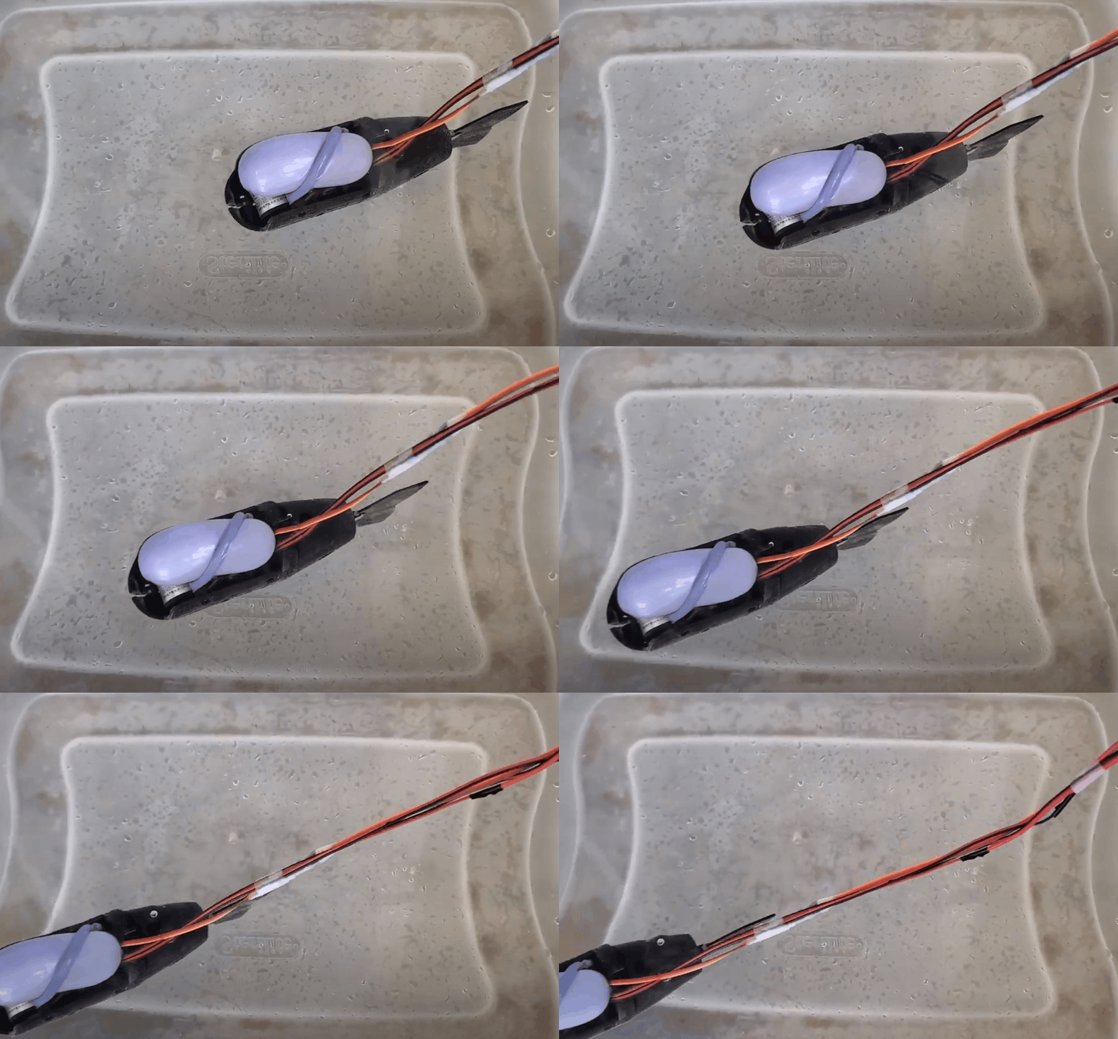
With this system, it should be very doable to make a fish that had completely on-board power and computing, which would allow us to control the fish without needing to account for how the tether influences its swimming pattern.